|
New demands for increased fuel efficiency, lower emissions and improved passenger comfort are changing how automobile manufacturers approach vehicle design, presenting an array of challenges for the industry at large and mechanical testing specifically. For the past decade, Byron Saari, Principal R&D Engineer at MTS Systems, has been focusing on the testing challenges. “It started with some really interesting inquiries from leading-edge damper, or shock absorber, suppliers about 10 years ago,” Saari said. “They asked about an NVH system that would be suitable for testing a structure-borne noise phenomenon called “chuckle.” It turned out to be a tall order.” |
|
|
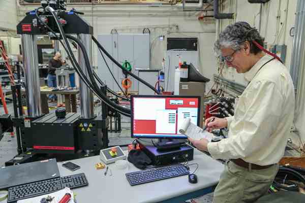
Byron Saari is integrating elastomer testing technology (foreground) and linear electro-magnetic actuation (background) to develop an effective means for studying structure-borne chuckle. |
|
|
What Saari was witnessing was the emergence of market forces that would soon complicate noise, vibration, and harshness (NVH) testing for dampers. The rise of autonomous vehicles, for example, is putting greater emphasis on ride and comfort. Lighter vehicles and quieter powertrains have improved fuel efficiency and reduced emissions but have also made it more difficult to control noise generated by (and transmitted by) the shock absorbers. In fact, now that powertrain, drivetrain, and aerodynamic noise have all been thoroughly reduced, residual damper noise is more prominent. While airborne “swish” is comparatively easy to identify and mitigate at the component level, structure-borne chuckle noise presents a more troubling issue. Chuckle (also called “clatter,” “rumble,” and “trunk of lumber”) has yet to be fully understood. It originates as a mechanical vibration in the body of the shock absorber. Impedance coupling in the upper mount turns the mechanical vibration into acoustic noise in the cab. As such, chuckle is model- or platform-dependent and cannot be easily identified or resolved at the component level. Serious chuckle problems are often discovered during the prototype phase and can be extremely disruptive to the vehicle development budget and schedule. Chuckle presents unique challenges for mechanical testing as well. Unlike swish analysis, chuckle testing has no standardized equipment or procedures. The phenomenon is difficult to replicate in the test lab because it is not always clear what noise signature will cause an issue. “Even if you can isolate a frequency that causes chuckle for a particular shock absorber, you may not be able to replicate it in a different test bench due to existing test system resonances,” Saari said. “All of these issues make it very difficult for damper suppliers to meet OEM specifications for damper noise in the cab. As a result, NVH testing has become a much more critical part of the development process.” Conventional damper test equipment is not well suited for characterizing chuckle. The mechanical vibration needs to be measured with an accelerometer at the top of the damper rod, which is difficult to do at high frequencies without the test rig influencing the results. In addition, damper test systems are typically used to run tests with a maximum input (sinusoidal or road data) of 25 Hz. If higher frequencies are unintentionally excited in the test system, it is generally not a concern. Unfortunately, chuckle happens at frequencies from 200 Hz to 500 Hz. If a 25 Hz sinusoid excites a 250 Hz harmonic, for example, it will be measured in the output of the piston rod. Analyzing this data would lead developers to conclude that the damper design has a 250 Hz chuckle problem, when in fact this is an effect of the harmonic distortion of the test system’s excitation. “To be truly effective at analyzing chuckle, a damper NVH solution needs to provide very pure sinusoidal excitation with very little total harmonic distortion, or THD,” Saari said. As it turns out, Saari is uniquely positioned to develop such a solution due to his many years at MTS spent researching and developing servohydraulic test systems for both damper and elastomer test applications. His work with customers worldwide helped shape both portfolios of products for the company, and he acquired deep domain expertise in the nuances of these complex tests. With insight from both domains, Saari envisioned a new test system design for studying damper NVH, one that would combine the capabilities of an elastomer test system with those of a damper test system. In 2014, MTS acquired Roehrig Engineering, Inc., developer of all-electric EMA damper test systems - renowned for high frequency response and programmability. The addition of linear Electro-Magnetic Actuation (EMA) technology provided the spark to set the new damper NVH solution in motion. The realization of Saari‘s damper NVH vision, then, would represent a fusion of conventional MTS elastomer with damper technologies and electro-magnetic actuation. |
|
|
The Model 853 NVH Damper System draws from servohydraulic damper (left), linear electro-magnetic damper (middle) and servohydraulic elastomer (right) test technologies. |
 |
|
To perform damper NVH measurements with fidelity and accuracy up to the required 700 Hz, the system would employ high-bandwidth transducers that are typically used to measure displacement, force, and vibration in high-frequency elastomer test systems. It would also need an elastomer test system’s high-stiffness load frame, along with larger diameter columns, a thicker crosshead, and a more robust base to avoid the resonant modes that can corrupt measurements. |
|
|
The first modal frequency affecting data measurements of interest is above 700 Hz. |
 |
|
Linear EMA technology is an ideal source for the clean sinusoidal input and low harmonic distortion the system would require for effective chuckle testing. MTS’ EMA technology combines fixed, high-force neodymium magnets and moving air-core (ironless) electric motors. The lack of ferrous metal makes the motor extremely lightweight, which is what enables the actuator’s high frequency response and high acceleration. The ironless motor also means there is no attractive force between the motor and the magnet and therefore no risk of cogging effects that can compromise the velocity waveform. |
|
|
Command (blue) vs. Response (red), indicating low Total Harmonic Distortion (THD) for a 15 Hz excitation. |
 |
|
The result of this fusion is the Model 853 NVH Damper System – purpose-built for NVH testing of dampers and shock absorbers. Specification-wise, the system will perform measurements with fidelity and accuracy up to 700 Hz. It will be rated at 15 to 20 kN, deliver 3 m/s simultaneous dynamic force and velocity and 1 kN static force standard with optional increased capacity. Versatile FlexTest® controller technology will make the system capable of reproducing virtually any type of signal (sine block, sweeps, road signals). In addition, high bandwidth PIDF (Proportional Integral Derivative Feedforward) control will enable it to follow a specified wave shape precisely without iterations. |
|
|
The Model 853 NVH Damper System – purpose-built for NVH testing of dampers and shock absorbers. |
 |
|
Saari believes the Model 853 will help test labs perform chuckle testing more easily, address the entire range of standard damper noise phenomena, including swish and squeak, perform basic damper characterization, and even provide elastomer testing functionality. “This new system will be an important advance in the field of NVH testing,” Saari said. “It fills a critical gap in damper test labs and gives test teams the standardized equipment necessary to address a persistent issue in the development cycle.” |
|
Adapting to Evolving Damper NVH Requirements
Learn how state-of-the-art MTS damper test solutions can benefit your new vehicle development.
Contact your MTS RepresentativeResources
Model 853 Damper NVH System
Analyze the complete spectrum of damper noise and vibration …
Faktoren, die bei der Abwägung von elektrischen oder hydraulischen Prüfsystemen zu berücksichtigen sind
Leitfaden für Dämpferprüfsysteme und Straßensimulatoren
Prüfen von leistungsstarken Fahrradaufhängungen
Besichtigen Sie das Testlabor der Fox Factory, Inc. und sehe…
Beschleunigung der aktiven und semiaktiven Systementwicklung
Entdecken Sie die Vorteile der bewährten mHIL-Technologie…
Nissan Motor Co., Ltd.
Verwendung der hybriden Simulation zur Bewertung der Auswirk…
Einführung in FlexTest Elite Performance-Regler
Kanalanzahl, Systemrate und Rechenkapazität erhöhen
Der Weg zu RPC Connect
Cody Johnson erforscht RPC-Software – Vergangenheit, Gegenwa…
Vorschau auf die RPC Connect-Software: Webinar 1
Safa Mogharebi erkundet die neue grafische Benutzeroberfläch…
Vorschau auf die RPC Connect-Software: Webinar 2
Safa Mogharebi erkundet die neuen Einrichtungs- und Analysep…
Vorschau auf die RPC Connect-Software: Webinar 3
Safa Mogharebi erkundet die neuen Modell- und Simulierungsph…
Prüfstandgestaltung
Bauen Sie Ihre eigenen hochwertigen, rekonfigurierbaren Komp…
Flat-Trac-Systeme der neuen Generation
Permanentmagnetmotoren von MTS verbessern Drehmomentkapaz…
Einführung eines vollelektrischen, langlebigen, reifengekoppelten Straßensimulators des Modells 320
Mit Eisenkern-Linearantrieben von MTS
Neuland für Reifentests
NTRC rüstet die weltweit leistungsfähigste Reifentestanla…
Optimale Abtastrate für servohydraulische Systeme
Brad Thoen untersucht, wie sich die Abtastrate des Systems a…
National Tire Research Center (NTRC): Transformation der Reifenkonstruktion
Das leistungsstarke Reifenprüfsystem von MTS ermöglicht H…
Vorteile durch die virtuelle Prüfung
Verwendung von Analysewerkzeugen zur Ableitung genauer Laste…
Neue Online-Schulungen verfügbar
Live-Einführungskurse zu unseren gängigsten Software-Plattfo…
Lebensdauerprüfung für Schwerlaster
Testtechnologien und -methoden für Schwerlaster erkunden.…
Fahrgestell-NVH-Prüfung
GNTP Komponenten- und Buchsen-NVH-Prüfstände.
Reifenprüfung für Leicht-Lkw und Rennsport
Flat-Trac LTRe Reifenkraft- und Moment-Messsystem
Der richtige 4-Poster: Servohydraulisch oder elektrisch?
Faktoren, die beim Abwägen von Servohydraulik und Elektri…