
Landmark® Servohydraulic Test Systems
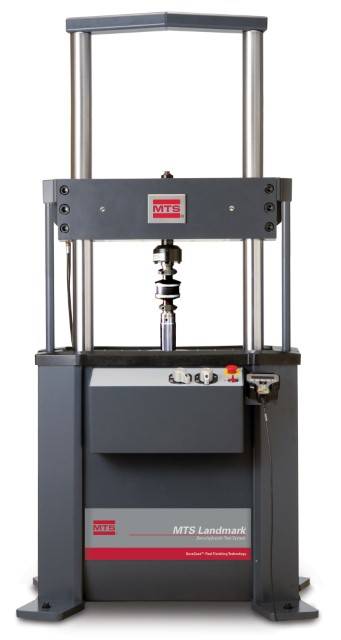
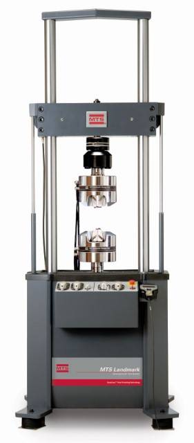
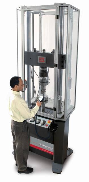
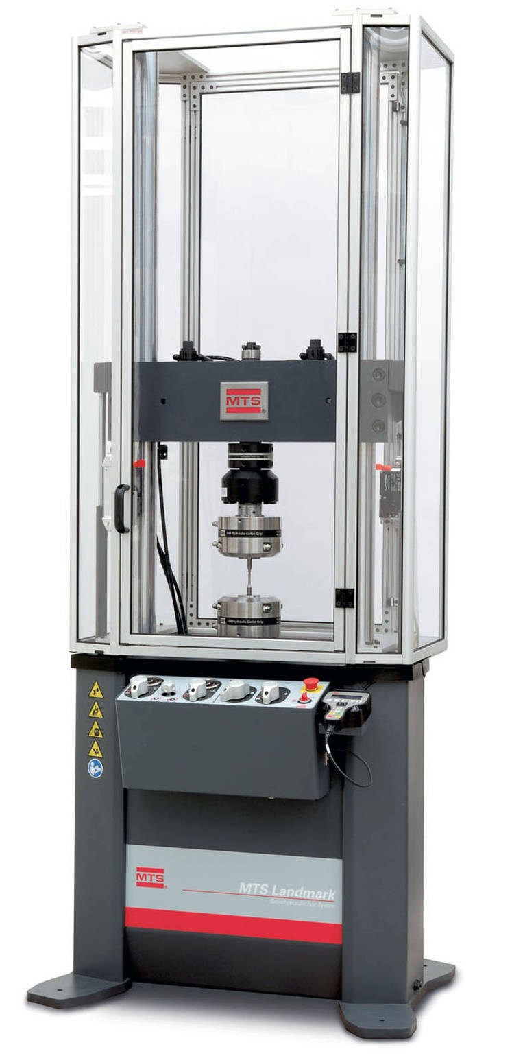
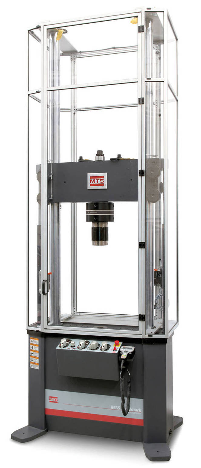
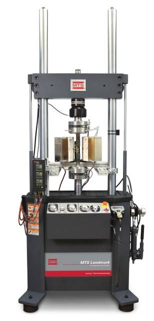
From complex thermomechanical fatigue studies to standard tension and compression tests, MTS Landmark systems deliver accurate, repeatable results. Robustly manufactured with SureCoat® technology that extends actuator rod longevity 10x over conventionally chrome-plated rods, these systems will perform reliably for years. SHOW UPDATE
Applications
Test Specimens
Test Standards
Key Product Features
Industry Standard
A proven leader in servohydraulic testing technology UPDATE
Accurate / Repeatable Results
Superior frame stiffness and alignment produces accurate results
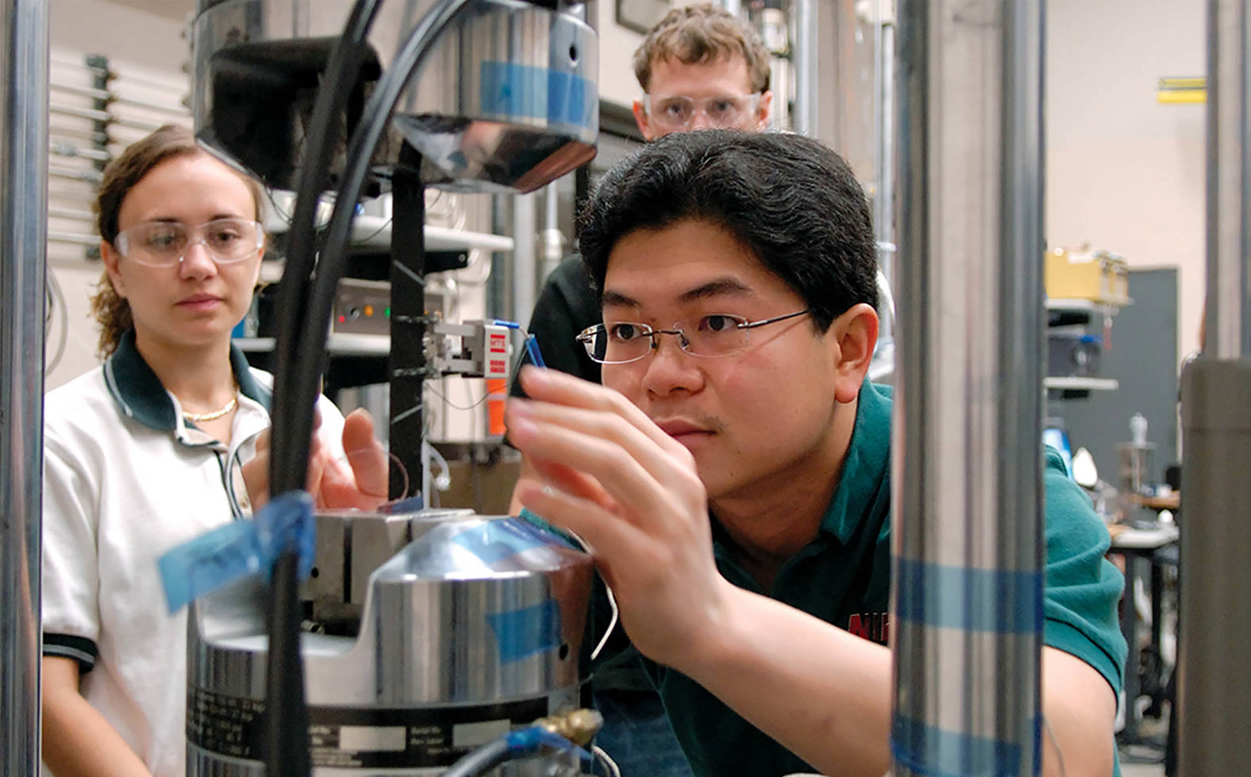
Unmatched Expertise
Applications expertise and service and support
Versatile
A wide array of test capabilities for low- to high-force applications
Featured Case Studies
Full Product Information
Floor-Standing Load Frame Specifications
|
LOAD FRAME |
DIAGRAM |
|
|
|
MODEL |
|
|
|
|
SPECIFICATIONS¹ |
DETAIL |
UNITS |
370.10 |
|
370.25 |
|
370.50 |
|
|
|
|
|
Actuator |
Actuator |
Actuator |
Actuator |
Actuator |
Actuator |
|
|
|
|
integral |
integral to |
integral |
integral to |
integral |
integral to |
|
|
|
|
to Base |
Crosshead |
to Base |
Crosshead |
to Base |
Crosshead |
|
Force capacity |
|
kN |
1000 |
100 |
250 |
250 |
500 |
500 |
|
(rated dynamic force) |
|
(kip) |
(22) |
(22) |
(55) |
(55) |
(110) |
(110) |
|
Available actuator ratings₁ (nominal) |
kN |
15, 25, 50, 100 |
15, 25, 50, 100 |
100, 250 |
100, 250 |
250, 500 |
250, 500 |
|
|
|
|
(kip) |
(3.3, 5.5, 11, 22) |
(3.3, 5.5, 11, 22) |
(22, 55) |
(22, 55) |
(55, 110) |
(55, 110) |
|
Actuator dynamic stroke₁ |
|
mm |
100, 150, 250 |
100, 150, 250 |
150, 250 |
150, 250 |
150 |
150 |
|
|
|
(in) |
(4, 6, 10) |
(4, 6, 10) |
(6, 10) |
(6, 10) |
(6) |
(6) |
|
Min vertical test space - |
A |
mm |
140 |
70 |
231 |
159 |
427 |
345 |
|
standard height₂ |
|
(in) |
(5.5) |
(2.8) |
(9.1) |
(6.3) |
(16.8) |
(13.6) |
|
Max vertical test space - |
A |
mm |
1283 |
1213 |
1621 |
1549 |
2085 |
2002 |
|
standard height₃ |
|
(in) |
(50.5) |
(47.8) |
(63.8) |
(61.0) |
(82.1) |
(78.8) |
|
Min vertical test space - |
A |
mm |
363 |
292 |
485 |
413 |
NA |
NA |
|
extended height₂ |
|
(in) |
(14.3) |
(11.5) |
(19.1) |
(16.3) |
NA |
NA |
|
Max vertical test space - |
A |
mm |
1753 |
1683 |
2129 |
2058 |
NA |
NA |
|
extended height₃ |
|
(in) |
(69.0) |
(66.3) |
(83.8) |
(81.0) |
NA |
NA |
|
Working height₄ |
B |
mm |
922₈, ₁₅ |
922₁₅ |
922₈, ₁₅ |
922₁₅ |
922₁₅ |
922₁₅ |
|
|
|
(in) |
(36.3) |
(36.3) |
(36.3) |
(36.3) |
(36.3) |
(36.3) |
|
Column spacing |
C |
mm |
533 |
533 |
635 |
635 |
762 |
762 |
|
(test space width) |
|
(in) |
(21.0) |
(21.0) |
(25.0) |
(25.0) |
(30.0) |
(30.0) |
|
Column diameter |
D |
mm |
76.2 |
76.2 |
76.2 |
76.2 |
101.6 |
101.6 |
|
|
|
(in) |
(3.00) |
(3.00) |
(3.00) |
(3.00) |
(4.00) |
(4.00) |
|
Base width |
E |
mm |
1018 |
1018 |
1112 |
1112 |
1351 |
1351 |
|
|
|
(in) |
(40.1) |
(40.1) |
(43.8) |
(43.8) |
(53.2) |
(53.2) |
|
Base depth |
F |
mm |
698 |
698 |
737 |
737 |
896 |
896 |
|
|
|
(in) |
(27.5) |
(27.5) |
(29.0) |
(29.0) |
(35.3) |
(35.3) |
|
Diagonal clearance - |
G |
mm |
2580₈, ₁₁, ₁₅ |
2649₁₁, ₁₅ |
3084₈, ₁₁, ₁₅ |
3155₁₁, ₁₅ |
3629₁₁, ₁₅ |
3699₁₁, ₁₅ |
|
standard height₅ |
|
(in) |
(101.6) |
(104.3) |
(121.4) |
(124.2) |
(142.9) |
(145.6) |
|
Diagonal clearance - |
G |
mm |
3084₈, ₁₁, ₁₅ |
3153₁₁, ₁₅ |
3589₈, ₁₁, ₁₅ |
3660₁₁, ₁₅ |
NA |
NA |
|
extended height₅ |
|
(in) |
(121.4) |
(124.1) |
(141.3) |
(144.1) |
NA |
NA |
|
Overall height - |
H |
mm |
2588₈, ₁₂, ₁₅ |
3028₉, ₁₅ |
3095₈, ₁₄, ₁₅ |
3490₁₀, ₁₅ |
3688 |
3961 |
|
standard height₆ |
|
(in) |
(101.9) |
(119.2) |
(121.8) |
(137.4) |
(145.2) |
(155.9) |
|
Overall height - |
H |
N/m |
3058₈, ₁₃, ₁₅ |
3498₉, ₁₅ |
3603₈, ₁₄, ₁₅ |
3998₁₀, ₁₅ |
NA |
NA |
|
extended height₆ |
|
(in) |
(120.4) |
(137.7) |
(141.8) |
(157.4) |
NA |
NA |
|
Stiffness₇ |
|
N/m |
467 x 10⁶ |
467 x 10⁶ |
473 x 10⁶ |
473 x 10⁶ |
777 x 10⁶ |
777 x 10⁶ |
|
|
|
(lbf/in) |
(2.66 x 10⁶) |
(2.66 x 10⁶) |
(2.7 x 10⁶) |
(2.7 x 10⁶) |
(4.44 x 10⁶) |
(4.44 x 10⁶) |
|
Weight |
|
kg |
635 |
820 |
875 |
1095 |
1570 |
1760 |
|
|
|
(lb) |
(1400) |
(1800) |
(1925) |
(2410) |
(3455) |
(3875) |
|
|
|
|
|
|
|
|
|
|
|
1.All load frame specifications listed in this chart are based upon the actuator ratings and dynamic stroke values indicated by bold text. |
|
|
||||||
|
2.Min Vertical Test Space: Span between force transducer and piston rod face when fully retracted at beginning of the dynamic stroke; crosshead down, no alignment fixture. |
||||||||
|
3.Max Vertical Test Space: Span between force transducer and piston rod face when fully retracted at beginning of the dynamic stroke; crosshead up, no alignment fixture. |
||||||||
|
4.Working Height: Floor to top of work surface; includes standard FabCell isolation. |
|
|
|
|
|
|||
|
5.Diagonal Clearance: Column height (far side) to tip of foot with FabCell; tie bar or enclosure not included. |
|
|
|
|||||
|
6.Overall Height: From floor, including standard FabCell isolation, to the highest point on crosshead; crosshead fully raised (most common stroke length). |
|
|||||||
|
7.Measured at typical testing height with hydraulic wedge grips and cylindrical dog-bone specimen. |
|
|
|
|
||||
|
Typical testing heights per model: Model 370.10 = 750 mm (29.5 in); Model 370.25 = 900 mm (35.5 in); Model 370.50 = 1250 mm (49.2 in) |
|
|
||||||
|
8.Add 178 mm (7 in) to dimensions B, G, & H for 250 mm (10 in) stroke actuators integral to base. |
|
|
|
|
||||
|
9.Add 229 mm (9 in) to dimension H for 250 mm (10 in) stroke actuators integral to crosshead. |
|
|
|
|
||||
|
10. Add 203 mm (8 in) to dimension H for 250 mm (10 in) stroke actuators integral to crosshead. |
|
|
|
|
||||
|
11. For frames with an optional tie bar add 51 mm (2 in) to dimension G. |
|
|
|
|
|
|||
|
12. For 370.10 frames with standard columns, optional tie bar and actuator integral to base add 14 mm (.53 in) to dimension H. |
|
|
||||||
|
13. For 370.10 frames with extended columns, optional tie bar and actuator integral to base add 51 mm (2 in) to dimension H. |
|
|
||||||
|
14. For 370.25 frames with standard or extended columns, optional tie bar and actuator integral to base add 14 mm (.53 in) to dimension H. |
|
|||||||
|
15. For load frames with optional pneumatic /elastomeric vibration isolation mounts, add 62 mm (2.44 in) to dimensions B, G, and H. |
|
|
||||||
|
LOAD FRAME |
DIAGRAM |
|
MODEL |
|
SPECIFICATIONS1 |
DETAIL |
UNITS |
370.10 200 Hz Elastomer |
|
Force capacity |
|
kN |
100 |
|
(rated dynamic force) |
|
(kip) |
(22) |
|
Available actuator ratings₁ (nominal) |
kN |
15, 25 |
|
|
|
|
(kip) |
(3.3, 5.5) |
|
Actuator dynamic stroke₁ |
|
mm |
100 |
|
|
|
(in) |
(4) |
|
Min vertical test space - |
A |
mm |
0 |
|
standard height₂ |
|
(in) |
0 |
|
Max vertical test space - |
A |
mm |
788 |
|
standard height₃ |
|
(in) |
(31.0) |
|
Working height₄ |
B |
mm |
922 |
|
|
|
(in) |
(36.3) |
|
Column spacing |
C |
mm |
533 |
|
(test space width) |
|
(in) |
(21.0) |
|
Column diameter |
D |
mm |
76.2 |
|
|
|
(in) |
(3.00) |
|
Base width |
E |
mm |
1018 |
|
|
|
(in) |
(40.1) |
|
Base depth |
F |
mm |
698 |
|
|
|
(in) |
(27.5) |
|
Diagonal clearance₅ |
G |
mm |
2079₈ |
|
|
|
(in) |
(81.8) |
|
Overall height₆ |
H |
mm |
2065₉ |
|
|
|
(in) |
(81.3) |
|
Stiffness₇ |
|
N/m |
467 x 10⁶ |
|
|
|
(lb/in) |
(2.66 x 10⁶) |
|
Weight |
|
kg |
635 |
|
|
|
(lb) |
(1400) |
|
|
|
|
|
|
1.All load frame specifications listed in this chart are based upon the actuator ratings and dynamic stroke values indicated by bold text. |
|||
|
2.Min Vertical Test Space: Span between force transducer and piston rod face when fully retracted at beginning of the dynamic stroke; crosshead down, no alignment fixture. |
|||
|
3.Max Vertical Test Space: Span between force transducer and piston rod face when fully retracted at beginning of the dynamic stroke; crosshead up, no alignment fixture. |
|||
|
4.Working Height: Floor to top of work surface; includes standard FabCell isolation. |
|||
|
5.Diagonal Clearance: Column height (far side) to tip of foot with FabCell; tie bar or enclosure not included. |
|||
|
6.Overall Height: From floor, including standard FabCell isolation, to the highest point on crosshead; crosshead fully raised (most common stroke length). |
|||
|
7.Measured at crosshead height of 750 mm (29.5 in). |
|
||
|
8.For frames with an optional tie bar add 51 mm (2 in) to dimension G. |
|||
|
9.For 370.10 200 Hz elastomer frames with an optional tie bar add 28 mm (1.1 in) to dimension H. |
|||




Service and Support
Our experts are here to help keep you up and running.