Series 311 High-Force Test Systems
Ultra-stiff, four-column servohydraulic load frames, dynamically rated to deliver loads ranging from 1 to 30 MN. Higher capacity load frames and unique features can be custom engineered to order.
Applications
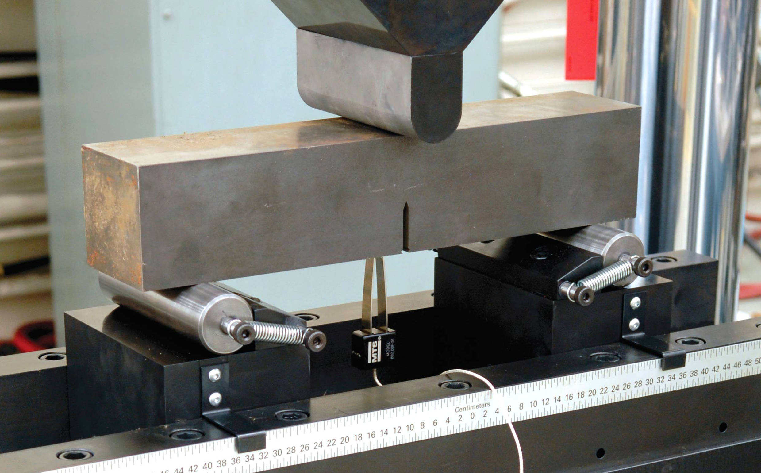
- Piegatura
- Compressione
- Test dinamici
- Fatica
- Frattura e fatica
- Tensione
- Misurazione di forza e rigidità
Test Specimens
- Cemento
- Materiali
- Pannelli per velivoli
- Sotto-componenti per pale per turbine eoliche
- Materiali da costruzione
- Metalli
- Tubazioni e tubature
- Armatura
- Catena
- Acciaio strutturale
- Filo e cavo
Key Product Features
Industry Standard
A proven leader in developing servohydraulic technology
Versatile
Dozens of available accessories including bending fixtures, compression platens and high force grips are available to provide a wide range of testing capabilities
Accurate/Repeatable Results
Superior frame stiffness and alignment produces accurate results
High Performance
Systems can be engineered with higher performance packages to meet any testing requirement
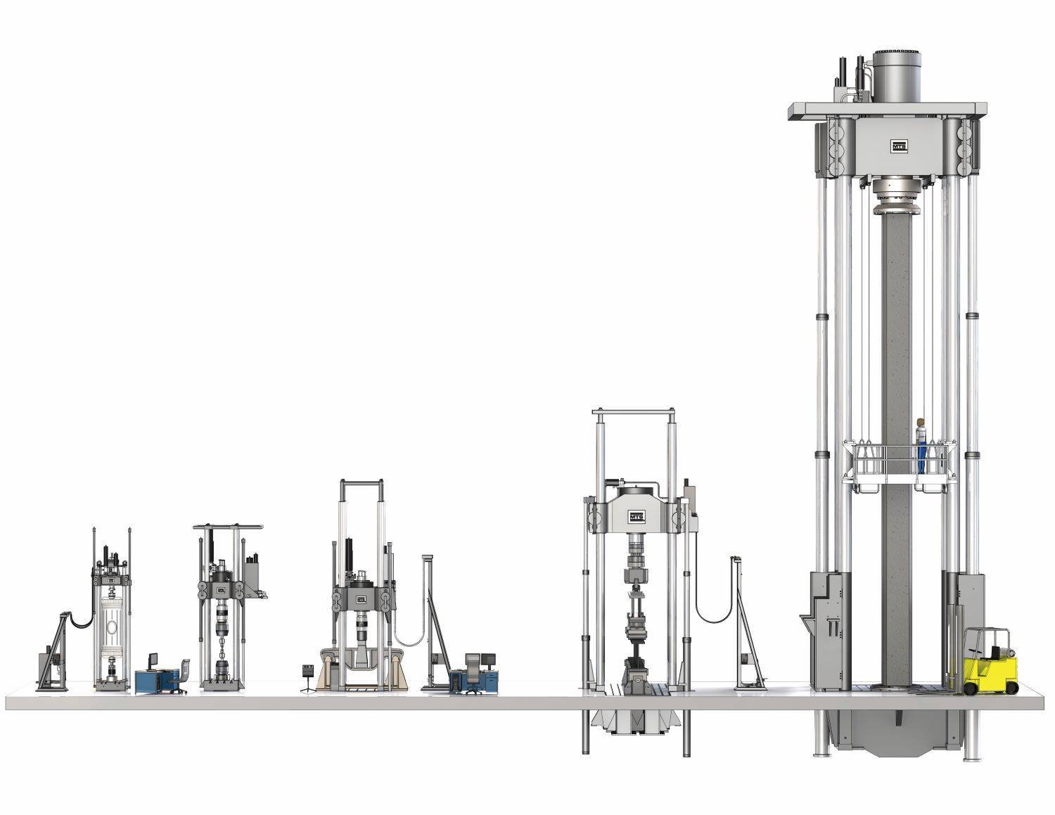
Model Comparison
311.31 / 311.32
- Max force capacity: 1.0 MN / 1.2MN (265 kip)
- Column Diameter: 4 inches
- Load Frame Height: Approx. 5.5m (8 ft)
- Load Frame Weight: Approx. 4100 kg (9100 lb)
- Customized models and performance packages available
311.41
- Max force capacity: 2.5MN (550 kip)
- Column Diameter: 6 inches
- Load Frame Height: Approx. 6.7m (22 ft)
- Load Frame Weight: Approx. 9525 kg (21,000 lb)
- Customized models and performance packages available
311.51
- Max force capacity: 5MN (1100 kip)
- Column Diameter: 8 inches
- Load Frame Height: Approx. 8.5m (28 ft)
- Load Frame Weight: Approx. 21,500 kg (47,500 lb)
- Customized models and performance packages available
311.71
- Max force capacity: 10MN (2200 kip)
- Column Diameter: 10 inches
- Load Frame Height: Approx. 11m (36 ft)
- Load Frame Weight: Approx. 55,000 kg (120,000 lb)
- Customized models and performance packages available
311.91
- Max force capacity: 30MN (6600 kip)
- Column Diameter: 17 inches (425mm)
- Load Frame Height: Approx. 20m ( 65ft)
- Load Frame Weight: Approx. 275,000 kg (600,000lb)
- Customized models and performance packages available
Featured Case Studies
Full Product Information

|
1. |
Optional Tie Bar |
|
2. |
High-Accuracy Linear Variable Differential Transducer (LVDT) |
|
3. |
Precision-machined, ultra-stiff columns |
|
4. |
Optional Hydraulic Crosshead Positioning Cylinders |
|
5. |
High-Stiffness Crosshead - Integrated Actuator - Integrated Hydraulic Manifold - Close-coupled Accumulators |
|
6. |
Optional Hose Stand |
|
7. |
Hydraulic Service Manifold (HSM) - Optional hose stand-mounted - Optional crosshead-mounted (shown) - Optional floor-standing |
|
8. |
Crosshead Lift/Lock Controls - Optional hose stand-mounted (shown) - Optional floor-standing |
|
9. |
Optional Hydraulic Grip Supply |
|
10. |
Load Frame Base Options - Standard T-Slot (shown) - Integrated Strong Floor |
|
11. |
Precision Force Transducer - Base-mounted (shown) - Actuator-mounted |
|
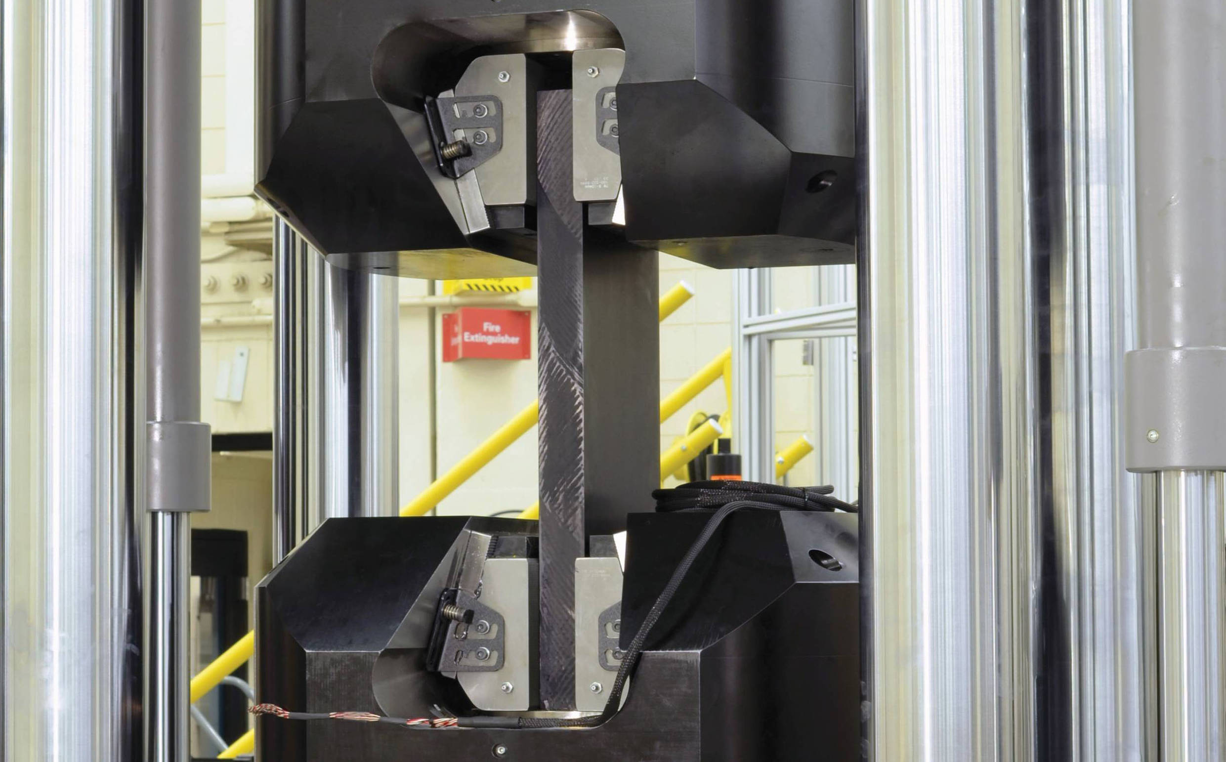
12. |
Optional High-Force Accessories - Compression Platens - Hydraulic Wedge Grips (shown) - Bend Fixtures - Custom Fixtures |
|
13. |
Crosshead Clamping Mechanism |
|
14. |
High-Performance MTS Actuator - Crosshead-mounted - High-Stiffness - Doubled-ended - Dynamically rated |
|
|
|
Standard Models |
Custom Models |
||||||
|
Load Frame Specifications |
Units |
311.31 |
311.32 |
311.41 |
311.51 |
311.61 |
311.71 |
311.81 |
311.91 |
|
Dynamic Force Ratings |
kN |
1000 |
1200 |
2500 |
5000 |
7500 |
10,000 |
20,000 |
30,000 |
|
(kip) |
(220) |
(265) |
(550) |
(1100) |
(1650) |
(2200) |
(4400) |
(6600) |
|
|
Standard Dynamic Strokes |
mm |
150, 250 |
150, 250 |
150, 300 |
300 |
Custom load frame dimensions vary according to customers' specific application requirements. Consult an MTS Applications Engineer for more information. |
|||
|
(in) |
(6, 10) |
(6, 10) |
(6,12) |
(12) |
|||||
|
Column Diameter |
mm |
101.6 |
101.6 |
152.4 |
203.2 |
||||
|
(in) |
(4.00) |
(4.00) |
(6.00) |
(8.00) |
|||||
|
Column Spacing (width) |
mm |
711.2 |
711.2 |
762 |
1016.0 |
||||
|
(in) |
(28.0) |
(28.0) |
(30.0) |
(40.0) |
|||||
|
Column Spacing (depth) |
mm |
406.4 |
406.4 |
508.0 |
812.8 |
||||
|
(in) |
(16.0) |
(16.0) |
(20.0) |
(32.0) |
|||||
|
Load Frame Height |
mm |
2946-5486 |
2946-5486 |
Note3 |
4470-8534 |
||||
|
(min-max) |
(in) |
(116-216) |
(116-216) |
Note3 |
(176-336) |
||||
|
Specimen and Grip Spacing |
mm |
254-2794 |
254-2794 |
Note2 |
450-4500 |
||||
|
(min-max) |
(in) |
(10-110) |
(10-110) |
Note2 |
(17.8-177) |
||||
|
Base Width (width) |
mm |
914.4 |
914.4 |
1066.8 |
1422.4 |
||||
|
(in) |
(36.0) |
(36.0) |
(42.0) |
(56.0) |
|||||
|
Base Width (including lifts) |
mm |
1219 |
1219 |
1492.5 |
1903 |
||||
|
(in) |
(48.0) |
(48.0) |
(58.8) |
(75.0) |
|||||
|
Base Depth |
mm |
1016 |
1016 |
1168.4 |
1397 |
||||
|
(in) |
(40.0) |
(40.0) |
(46.0) |
(55.0) |
|||||
|
Base Height (from floor) |
mm |
280.9 |
280.9 |
332 |
450 |
||||
|
(in) |
(11.06) |
(11.06) |
(13.06) |
(17.8) |
|||||
|
Hose Stand Spacing (max) |
mm |
921 |
921 |
2479 |
2479 |
||||
|
(in) |
(36.3) |
(36.3) |
(97.7) |
(97.7) |
|||||
|
Hose Stand Width |
mm |
991 |
991 |
991 |
991 |
||||
|
(in) |
(39.0) |
(39.0) |
(39.0) |
(39.0) |
|||||
|
Hose Stand Depth |
mm |
688 |
688 |
688 |
688 |
||||
|
(in) |
(27.1) |
(27.1) |
(27.1) |
(27.1) |
|||||
|
Hose Stand Height |
mm |
2426 |
2426 |
2819 |
3200 |
||||
|
(in) |
(95.5) |
(95.5) |
(111.0) |
(126.0) |
|||||
|
Approximate Crosshead Weight |
kg |
1225 |
1225 |
2903 |
7938 |
||||
|
(lb) |
(2700) |
(2700) |
(6400) |
(17,500) |
|||||
|
Approximate Total Weight |
kg |
4100 |
4100 |
9525 |
21500 |
||||
|
(lb) |
(9100) |
(9100) |
(21,000) |
(47,500) |
|||||
|
System Stiffness4 |
N/m |
1.6 X 10⁹ |
1.6 X 10⁹ |
3.1 X 10⁹ |
3.9 X 10⁹ |
||||
|
lbf/in |
9.3 X 10⁶ |
9.3 X 10⁶ |
17.4 X 10⁶ |
22.6 X 10⁶ |
|||||
|
1.Model 311.31 & 311.32 with actuator retracted, 311.41 & 311.51 with actuator at mid-stroke |
|
2.Model 311.41 150 mm stroke is 400 – 3000 mm (15.75 – 118.1 in), 311.41 300 mm stroke is 400 – 3385 (13.31 – 133.3 in) |
|
3.Model 311.41 150 mm stroke is 3554 – 6154 (140.0 – 242.3 in), 311.41 300 mm stroke is 3720 – 6768 (146.5 – 266.5 in) |
|
4.Stiffness calculated at a crosshead height of 2 meters (78.7 inch) above the base. |
Service and Support
Our experts are here to help keep you up and running.
Related Products, Parts or Accessories
Landmark® Servohydraulic Test Systems
TestSuite Software
SilentFlo™ 515 Hydraulic Power Units (HPU)
Looking for more products?
Go to Solution FinderCONTACT US TODAY
Ready for a quote or need more information? We're here to help. Request A QuoteResources
Sfide dei test a forza elevata
Gli ingeneri applicativi MTS spiegano le differenze e le sfi…
Utilizzo di Performance C3 per velocizzare test strutturali complesse
Casi di utilizzo; NIAR & NRC–Canada
Test su tondini ad altissima resistenza
Soddisfare i requisiti di test delle armature ad altissima r…
Protezione dello stato di salute dei sistemi idraulici
Scopri i vantaggi del Programma di manutenzione dell'olio di…
Il caso della calibrazione
La calibrazione MTS può contribuire ad aumentare la validità…
Efficienza energetica maggiore dell'8%
Riduci i costi operativi della HPU SilentFlo 505 sostituendo…