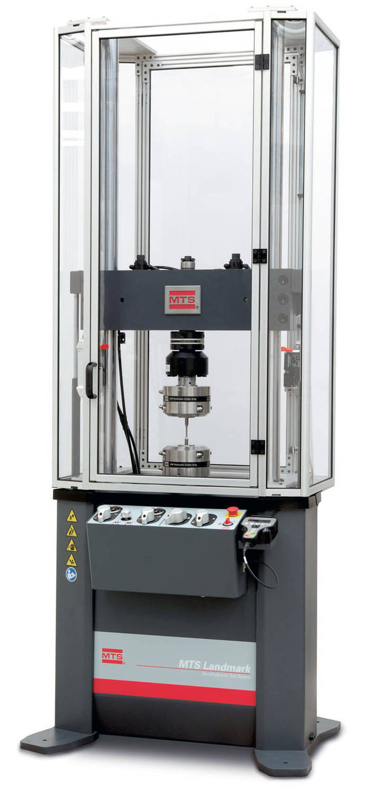
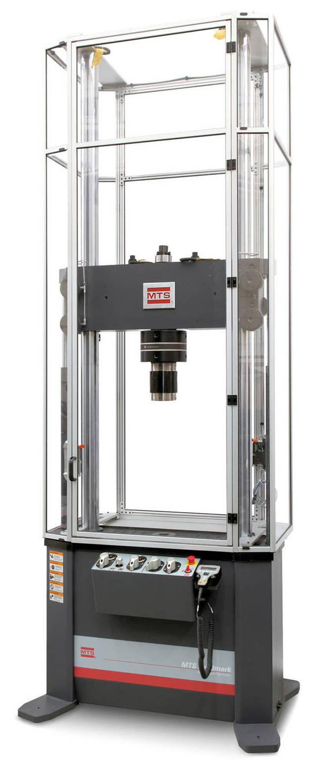
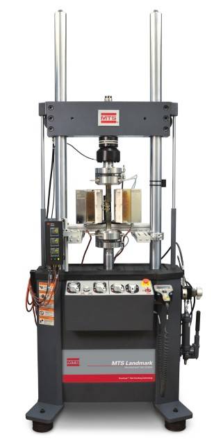
Landmark® Servohydraulic Test Systems
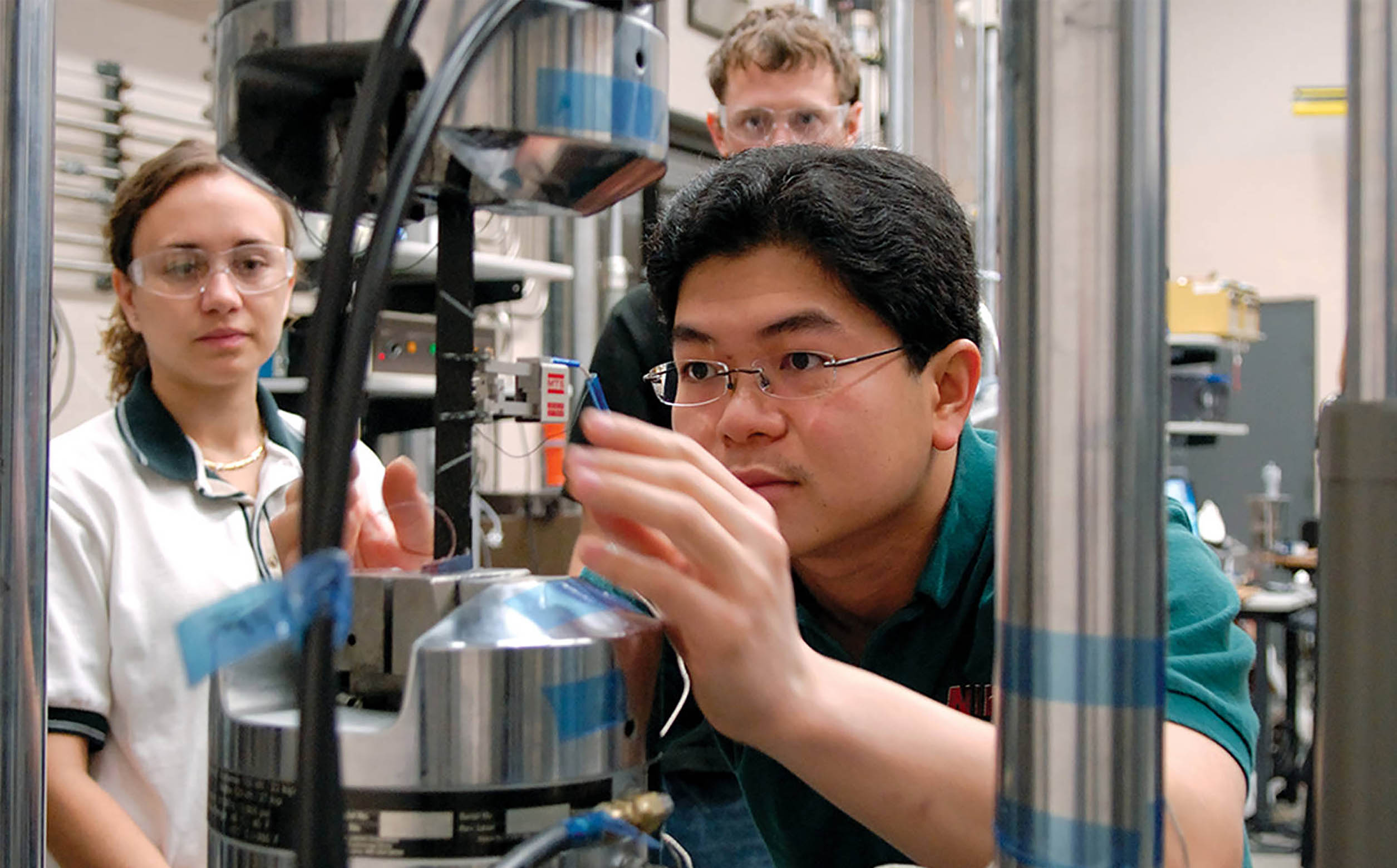
From complex thermomechanical fatigue studies to standard tension and compression tests, MTS Landmark systems deliver accurate, repeatable results. Robustly manufactured with SureCoat® technology that extends actuator rod longevity 10x over conventionally chrome-plated rods, these systems will perform reliably for years.
Applications
-
Dinámica cíclica
- Propagación de grietas
- CTOD (Desplazamiento de apertura de la punta de la grieta)
- Caracterización dinámica
- Análisis mecánico dinámico (DMA)
- Crecimiento de grieta por fatiga
- Fatiga de ciclo alto (HCF)
- High-temperature
- Jlc-CTOD
- Klc
- Fatiga de ciclo bajo (HCF)
- Pruebas estáticas
Test Specimens
-
Materiales compuestos
- Fibra de carbón
- Matriz de cerámica
- Materiales compuestos
- Matriz de metal
- Matriz de polímero
-
Polímeros
- Materiales elastoméricos
- Elastómeros
- Plásticos
- Polímeros
- Caucho
- Cerámica
- Metales
- Componentes de dispositivos médicos
- Aluminio
Test Standards
- ASTM D3039
- ASTM D2344
- ASTM D790
- ASTM D3518
- ASTM D5023
- ASTM D5024
- ASTM D5026
- ASTM D5418
- ASTM D5992
- ASTM D6272
- ASTM D7028
- ASTM E21
- ASTM E290
- ASTM E517
- ASTM E646
- ASTM E8-E8M
- ASTM E9
- ISO 10113
- ISO 10275
- ISO 14125
- ISO 6892-1
- ISO 6892-2
- ISO 7438
- ISO 14129
- ISO 527-4
- ISO 527-5
- ISO 6721-4
- ISO 6721-12
- EN 2561
- EN 2562
- EN 2597
- EN 2746
- EN 6031
Key Product Features
Industry Standard
A proven leader in servohydraulic testing technology
Accurate / Repeatable Results
Superior frame stiffness and alignment produces accurate results
Unmatched Expertise
Applications expertise and service and support
Versatile
A wide array of test capabilities for low- to high-force applications
Featured Case Studies
Full Product Information
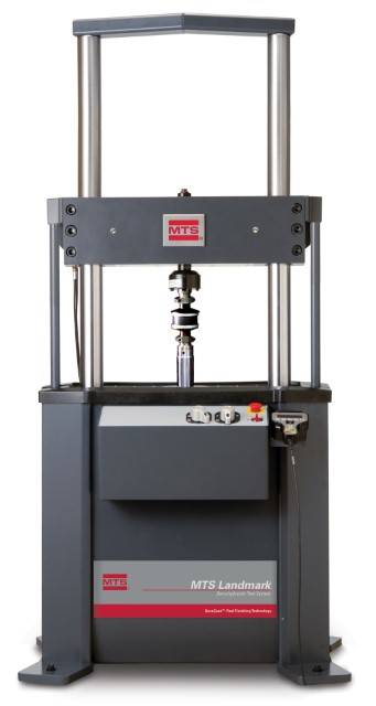
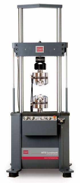
Floor-Standing Load Frame Specifications
|
LOAD FRAME |
DIAGRAM |
|
|
|
MODEL |
|
|
|
|
SPECIFICATIONS¹ |
DETAIL |
UNITS |
370.10 |
|
370.25 |
|
370.50 |
|
|
|
|
|
Actuator |
Actuator |
Actuator |
Actuator |
Actuator |
Actuator |
|
|
|
|
integral |
integral to |
integral |
integral to |
integral |
integral to |
|
|
|
|
to Base |
Crosshead |
to Base |
Crosshead |
to Base |
Crosshead |
|
Force capacity |
|
kN |
100 |
100 |
250 |
250 |
500 |
500 |
|
(rated dynamic force) |
|
(kip) |
(22) |
(22) |
(55) |
(55) |
(110) |
(110) |
|
Available actuator ratings₁ (nominal) |
kN |
15, 25, 50, 100 |
15, 25, 50, 100 |
100, 250 |
100, 250 |
250, 500 |
250, 500 |
|
|
|
|
(kip) |
(3.3, 5.5, 11, 22) |
(3.3, 5.5, 11, 22) |
(22, 55) |
(22, 55) |
(55, 110) |
(55, 110) |
|
Actuator dynamic stroke₁ |
|
mm |
100, 150, 250 |
100, 150, 250 |
150, 250 |
150, 250 |
150 |
150 |
|
|
|
(in) |
(4, 6, 10) |
(4, 6, 10) |
(6, 10) |
(6, 10) |
(6) |
(6) |
|
Min vertical test space - |
A |
mm |
140 |
70 |
231 |
159 |
427 |
345 |
|
standard height₂ |
|
(in) |
(5.5) |
(2.8) |
(9.1) |
(6.3) |
(16.8) |
(13.6) |
|
Max vertical test space - |
A |
mm |
1283 |
1213 |
1621 |
1549 |
2085 |
2002 |
|
standard height₃ |
|
(in) |
(50.5) |
(47.8) |
(63.8) |
(61.0) |
(82.1) |
(78.8) |
|
Min vertical test space - |
A |
mm |
363 |
292 |
485 |
413 |
NA |
NA |
|
extended height₂ |
|
(in) |
(14.3) |
(11.5) |
(19.1) |
(16.3) |
NA |
NA |
|
Max vertical test space - |
A |
mm |
1753 |
1683 |
2129 |
2058 |
NA |
NA |
|
extended height₃ |
|
(in) |
(69.0) |
(66.3) |
(83.8) |
(81.0) |
NA |
NA |
|
Working height₄ |
B |
mm |
922₈, ₁₅ |
922₁₅ |
922₈, ₁₅ |
922₁₅ |
922₁₅ |
922₁₅ |
|
|
|
(in) |
(36.3) |
(36.3) |
(36.3) |
(36.3) |
(36.3) |
(36.3) |
|
Column spacing |
C |
mm |
533 |
533 |
635 |
635 |
762 |
762 |
|
(test space width) |
|
(in) |
(21.0) |
(21.0) |
(25.0) |
(25.0) |
(30.0) |
(30.0) |
|
Column diameter |
D |
mm |
76.2 |
76.2 |
76.2 |
76.2 |
101.6 |
101.6 |
|
|
|
(in) |
(3.00) |
(3.00) |
(3.00) |
(3.00) |
(4.00) |
(4.00) |
|
Base width |
E |
mm |
1018 |
1018 |
1112 |
1112 |
1351 |
1351 |
|
|
|
(in) |
(40.1) |
(40.1) |
(43.8) |
(43.8) |
(53.2) |
(53.2) |
|
Base depth |
F |
mm |
698 |
698 |
737 |
737 |
896 |
896 |
|
|
|
(in) |
(27.5) |
(27.5) |
(29.0) |
(29.0) |
(35.3) |
(35.3) |
|
Diagonal clearance - |
G |
mm |
2580₈, ₁₁, ₁₅ |
2649₁₁, ₁₅ |
3084₈, ₁₁, ₁₅ |
3155₁₁, ₁₅ |
3629₁₁, ₁₅ |
3699₁₁, ₁₅ |
|
standard height₅ |
|
(in) |
(101.6) |
(104.3) |
(121.4) |
(124.2) |
(142.9) |
(145.6) |
|
Diagonal clearance - |
G |
mm |
3084₈, ₁₁, ₁₅ |
3153₁₁, ₁₅ |
3589₈, ₁₁, ₁₅ |
3660₁₁, ₁₅ |
NA |
NA |
|
extended height₅ |
|
(in) |
(121.4) |
(124.1) |
(141.3) |
(144.1) |
NA |
NA |
|
Overall height - |
H |
mm |
2588₈, ₁₂, ₁₅ |
3028₉, ₁₅ |
3095₈, ₁₄, ₁₅ |
3490₁₀, ₁₅ |
3688 |
3961 |
|
standard height₆ |
|
(in) |
(101.9) |
(119.2) |
(121.8) |
(137.4) |
(145.2) |
(155.9) |
|
Overall height - |
H |
N/m |
3058₈, ₁₃, ₁₅ |
3498₉, ₁₅ |
3603₈, ₁₄, ₁₅ |
3998₁₀, ₁₅ |
NA |
NA |
|
extended height₆ |
|
(in) |
(120.4) |
(137.7) |
(141.8) |
(157.4) |
NA |
NA |
|
Stiffness₇ |
|
N/m |
467 x 10⁶ |
467 x 10⁶ |
473 x 10⁶ |
473 x 10⁶ |
777 x 10⁶ |
777 x 10⁶ |
|
|
|
(lbf/in) |
(2.66 x 10⁶) |
(2.66 x 10⁶) |
(2.7 x 10⁶) |
(2.7 x 10⁶) |
(4.44 x 10⁶) |
(4.44 x 10⁶) |
|
Weight |
|
kg |
635 |
820 |
875 |
1095 |
1570 |
1760 |
|
|
|
(lb) |
(1400) |
(1800) |
(1925) |
(2410) |
(3455) |
(3875) |
|
|
|
|
|
|
|
|
|
|
|
1.All load frame specifications listed in this chart are based upon the actuator ratings and dynamic stroke values indicated by bold text. |
|
|
||||||
|
2.Min Vertical Test Space: Span between force transducer and piston rod face when fully retracted at beginning of the dynamic stroke; crosshead down, no alignment fixture. |
||||||||
|
3.Max Vertical Test Space: Span between force transducer and piston rod face when fully retracted at beginning of the dynamic stroke; crosshead up, no alignment fixture. |
||||||||
|
4.Working Height: Floor to top of work surface; includes standard FabCell isolation. |
|
|
|
|
|
|||
|
5.Diagonal Clearance: Column height (far side) to tip of foot with FabCell; tie bar or enclosure not included. |
|
|
|
|||||
|
6.Overall Height: From floor, including standard FabCell isolation, to the highest point on crosshead; crosshead fully raised (most common stroke length). |
|
|||||||
|
7.Measured at typical testing height with hydraulic wedge grips and cylindrical dog-bone specimen. |
|
|
|
|
||||
|
Typical testing heights per model: Model 370.10 = 750 mm (29.5 in); Model 370.25 = 900 mm (35.5 in); Model 370.50 = 1250 mm (49.2 in) |
|
|
||||||
|
8.Add 178 mm (7 in) to dimensions B, G, & H for 250 mm (10 in) stroke actuators integral to base. |
|
|
|
|
||||
|
9.Add 229 mm (9 in) to dimension H for 250 mm (10 in) stroke actuators integral to crosshead. |
|
|
|
|
||||
|
10. Add 203 mm (8 in) to dimension H for 250 mm (10 in) stroke actuators integral to crosshead. |
|
|
|
|
||||
|
11. For frames with an optional tie bar add 51 mm (2 in) to dimension G. |
|
|
|
|
|
|||
|
12. For 370.10 frames with standard columns, optional tie bar and actuator integral to base add 14 mm (.53 in) to dimension H. |
|
|
||||||
|
13. For 370.10 frames with extended columns, optional tie bar and actuator integral to base add 51 mm (2 in) to dimension H. |
|
|
||||||
|
14. For 370.25 frames with standard or extended columns, optional tie bar and actuator integral to base add 14 mm (.53 in) to dimension H. |
|
|||||||
|
15. For load frames with optional pneumatic /elastomeric vibration isolation mounts, add 62 mm (2.44 in) to dimensions B, G, and H. |
|
|
||||||
|
LOAD FRAME |
DIAGRAM |
|
MODEL |
|
SPECIFICATIONS1 |
DETAIL |
UNITS |
370.10 200 Hz Elastomer |
|
Force capacity |
|
kN |
100 |
|
(rated dynamic force) |
|
(kip) |
(22) |
|
Available actuator ratings₁ (nominal) |
kN |
15, 25 |
|
|
|
|
(kip) |
(3.3, 5.5) |
|
Actuator dynamic stroke₁ |
|
mm |
100 |
|
|
|
(in) |
(4) |
|
Min vertical test space - |
A |
mm |
0 |
|
standard height₂ |
|
(in) |
0 |
|
Max vertical test space - |
A |
mm |
788 |
|
standard height₃ |
|
(in) |
(31.0) |
|
Working height₄ |
B |
mm |
922 |
|
|
|
(in) |
(36.3) |
|
Column spacing |
C |
mm |
533 |
|
(test space width) |
|
(in) |
(21.0) |
|
Column diameter |
D |
mm |
76.2 |
|
|
|
(in) |
(3.00) |
|
Base width |
E |
mm |
1018 |
|
|
|
(in) |
(40.1) |
|
Base depth |
F |
mm |
698 |
|
|
|
(in) |
(27.5) |
|
Diagonal clearance₅ |
G |
mm |
2079₈ |
|
|
|
(in) |
(81.8) |
|
Overall height₆ |
H |
mm |
2065₉ |
|
|
|
(in) |
(81.3) |
|
Stiffness₇ |
|
N/m |
467 x 10⁶ |
|
|
|
(lb/in) |
(2.66 x 10⁶) |
|
Weight |
|
kg |
635 |
|
|
|
(lb) |
(1400) |
|
|
|
|
|
|
1.All load frame specifications listed in this chart are based upon the actuator ratings and dynamic stroke values indicated by bold text. |
|||
|
2.Min Vertical Test Space: Span between force transducer and piston rod face when fully retracted at beginning of the dynamic stroke; crosshead down, no alignment fixture. |
|||
|
3.Max Vertical Test Space: Span between force transducer and piston rod face when fully retracted at beginning of the dynamic stroke; crosshead up, no alignment fixture. |
|||
|
4.Working Height: Floor to top of work surface; includes standard FabCell isolation. |
|||
|
5.Diagonal Clearance: Column height (far side) to tip of foot with FabCell; tie bar or enclosure not included. |
|||
|
6.Overall Height: From floor, including standard FabCell isolation, to the highest point on crosshead; crosshead fully raised (most common stroke length). |
|||
|
7.Measured at crosshead height of 750 mm (29.5 in). |
|
||
|
8.For frames with an optional tie bar add 51 mm (2 in) to dimension G. |
|||
|
9.For 370.10 200 Hz elastomer frames with an optional tie bar add 28 mm (1.1 in) to dimension H. |
|||
|
Tabletop Load Frame Specifications |
|
Model 370.02 tabletop load frames are available standard or extended heights with the |
|
actuator configured integral to load frame crosshead. |
|
LOAD FRAME |
DIAGRAM |
|
MODEL |
|
|
SPECIFICATIONS₁ |
DETAIL |
UNITS |
370.02 |
370.02 100 Hz Elastomer |
|
Force capacity |
|
kN |
25 |
25 |
|
(rated dynamic force) |
|
(kip) |
(5.5) |
(5.5) |
|
Available actuator ratings₁ (nominal) |
|
kN |
15, 25 |
15, 25 |
|
|
|
(kip) |
(3.3, 5.5) |
(3.3, 5.5) |
|
Actuator dynamic stroke₁ |
|
mm |
100, 150 |
100, 150 |
|
|
|
(in) |
(4, 6) |
(4, 6) |
|
Min vertical test space - |
A |
mm |
144 |
144 |
|
standard height₂ |
|
(in) |
(5.7) |
(5.7) |
|
Max vertical test space - |
A |
mm |
827 |
827 |
|
standard height₃ |
|
(in) |
(32.6) |
(32.6) |
|
Min vertical test space - |
A |
mm |
398 |
398 |
|
extended height₂ |
|
(in) |
(15.7) |
(15.7) |
|
Max vertical test space - |
A |
mm |
1335 |
1335 |
|
extended height₃ |
|
(in) |
(52.6) |
(52.6) |
|
Working height₄ |
B |
mm |
230₈ |
230₈ |
|
|
|
(in) |
(9.1) |
(9.1) |
|
Column spacing |
C |
mm |
460 |
460 |
|
|
|
(in) |
(18.1) |
(18.1) |
|
Column diameter |
D |
mm |
76.2 |
76.2 |
|
(test space width) |
|
(in) |
(3.00) |
(3.00) |
|
Base width |
E |
mm |
622 |
622 |
|
|
|
(in) |
(24.5) |
(24.5) |
|
Base depth |
F |
mm |
577 |
577 |
|
|
|
(in) |
(22.7) |
(22.7) |
|
Diagonal clearance - |
G |
mm |
1750₈ |
1750₈ |
|
standard height₅ |
|
(in) |
(68.9) |
(68.9) |
|
Diagonal clearance - |
G |
mm |
2250₈ |
2250₈ |
|
extended height₅ |
|
(in) |
(88.6) |
(88.6) |
|
Overall height - |
H |
mm |
1989₈ |
1989₈ |
|
standard height₆ |
|
(in) |
(78.3) |
(78.3) |
|
Overall height - |
H |
mm |
2624₈ |
2624₈ |
|
extended height₆ |
|
(in) |
(103.3) |
(103.3) |
|
Stiffness₇ |
|
N/m |
345 x 10⁶ |
345 x 10⁶ |
|
|
|
(lb/in) |
(1.95 x 10⁶) |
(1.95 x 10⁶) |
|
Weight |
|
kg |
248 |
286 |
|
|
|
(lb) |
(547) |
(630) |
|
|
|
|
|
|
|
1.All load frame specifications listed in this chart are based upon the actuator ratings and dynamic stroke values indicated by bold text. |
||||
|
2.Min Vertical Test Space: Span between force transducer and piston rod face when fully retracted at beginning of the dynamic stroke; crosshead down, no alignment fixture. |
||||
|
3.Max Vertical Test Space: Span between force transducer and piston rod face when fully retracted at beginning of the dynamic stroke; crosshead up, no alignment fixture. |
||||
|
4.Working Height: Floor to top of work surface; includes standard FabCell isolation. |
|
|||
|
5.Diagonal Clearance: Hose height to tip of foot with FabCell; crosshead down. |
|
|||
|
6.Overall Height: From floor, including standard FabCell isolation, to top of the hoses or highest point on actuator; crosshead fully raised. |
||||
|
7.Measured at crosshead height of 600 mm (23.6 in). |
|
|
||
|
8.For load frames with optional pneumatic /elastomeric vibration isolation mounts, add 37 mm (1.44 in) to dimensions B, G, and H. |
||||

Our Smallest, Quietest HPU
The MTS SilentFlo 515.04 was specifically designed for use with a single MTS Landmark® or Bionix® load frame. For applications requiring a force range of 1–25 kN (0.2–5.5 kip) and a maximum average flow rate of 15.1 lpm (4 gpm), this HPU provides all the benefits of proven SilentFlo technology at a fraction of the cost.
MTS SilentFlo 515.04 HPU Brochure
Service and Support
Our experts are here to help keep you up and running.
Related Products, Parts or Accessories
Acumen® Electrodynamic Test Systems
Axial Extensometers with 50 mm (2 in.) Gage Length
Elevated High Temperature Axial Extensometer
TestSuite Software
Model 653 High-Temperature Furnaces
Advantage Video Extensometer (AVX)
Looking for more products?
Go to Solution FinderCONTACT US TODAY
Ready for a quote or need more information? We're here to help. Request A QuoteResources
Universidad Estatal de Florida
La Universidad avanza en las pruebas de barras de refuerzo r…
1D, 2D & 3D Non-Contacting Extensometers
Top considerations for choosing a non-contacting extensomete…
Load Frame Life Extension
An actuator remanufacture can extend the life of your older …
Cartilla de seguridad para los sistemas Landmark
Cómo cumplir con los requisitos de seguridad PLc, PLd o P…
Pruebas precisas de probetas pequeñas
Nuestras mordazas más pequeñas para sus probetas más pequeña…
29 consejos para protegerse del polvo y la suciedad en las pruebas de materiales compuestos
Evite que el polvo y los residuos dañen los equipos de prueb…
Evaluar las compensaciones de alta temperatura
Un científico del MTS analiza las opciones para las pruebas …
Incrementar la vida útil de los componentes y aligerar su peso
Los investigadores de la Universidad de Lehigh aprovechan el…
HPU de bajo consumo para pruebas de materiales
Nuestra HPU más pequeña es perfecta para aplicaciones dinámi…
Tecnología SureCoat para sistemas Landmark y Bionix
La tecnología patentada de acabado de la varilla del actuado…
Fabricación aditiva 101
Los expertos de MTS comparten conocimientos sobre la fabrica…
Nuevo extensómetro óptico
Medición y control simplificados de la deformación axial sin…
¿PL-c, PL-d or PL-e?
Cómo elegir el nivel de rendimiento de seguridad correcto.
Implantes de columna impresos en 3D
MTS ayuda a un fabricante de dispositivos médicos a desarrol…