Series 311 High-Force Test Systems
Ultra-stiff, four-column servohydraulic load frames, dynamically rated to deliver loads ranging from 1 to 30 MN. Higher capacity load frames and unique features can be custom engineered to order.
Applications
- Doblez
- Compresión
- Pruebas dinámicas
- Fatiga
- Fatiga y fractura
- Tensión
- Medición de la rigidez y la resistencia
Test Specimens
- Concreto
- Materiales
- Paneles de aviones
- Subcomponentes de las palas del aerogenerador
- Materiales de construcción
- Metales
- Tubos y tuberías
- Barras de refuerzo
- Cadena
- Acero estructural
- Alambre y cable
Key Product Features
Industry Standard
A proven leader in developing servohydraulic technology
Versatile
Dozens of available accessories including bending fixtures, compression platens and high force grips are available to provide a wide range of testing capabilities
Accurate/Repeatable Results
Superior frame stiffness and alignment produces accurate results
High Performance
Systems can be engineered with higher performance packages to meet any testing requirement
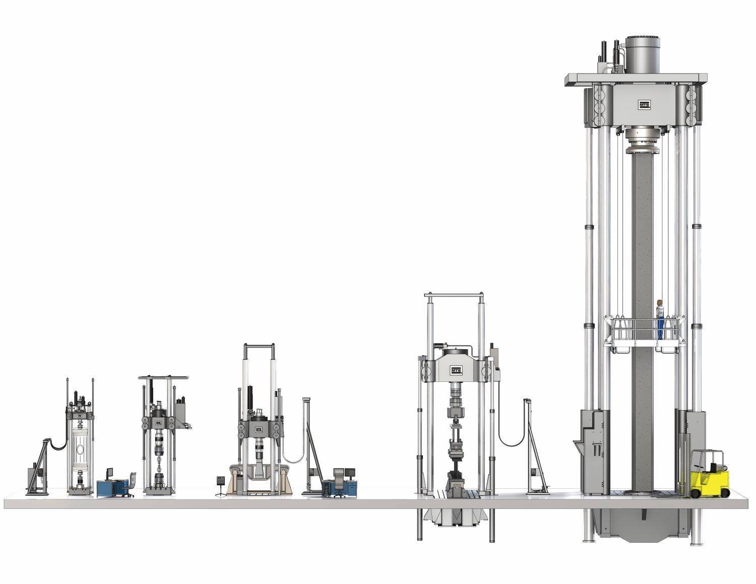
Model Comparison
311.31 / 311.32
- Max force capacity: 1.0 MN / 1.2MN (265 kip)
- Column Diameter: 4 inches
- Load Frame Height: Approx. 5.5m (8 ft)
- Load Frame Weight: Approx. 4100 kg (9100 lb)
- Customized models and performance packages available
311.41
- Max force capacity: 2.5MN (550 kip)
- Column Diameter: 6 inches
- Load Frame Height: Approx. 6.7m (22 ft)
- Load Frame Weight: Approx. 9525 kg (21,000 lb)
- Customized models and performance packages available
311.51
- Max force capacity: 5MN (1100 kip)
- Column Diameter: 8 inches
- Load Frame Height: Approx. 8.5m (28 ft)
- Load Frame Weight: Approx. 21,500 kg (47,500 lb)
- Customized models and performance packages available
311.71
- Max force capacity: 10MN (2200 kip)
- Column Diameter: 10 inches
- Load Frame Height: Approx. 11m (36 ft)
- Load Frame Weight: Approx. 55,000 kg (120,000 lb)
- Customized models and performance packages available
311.91
- Max force capacity: 30MN (6600 kip)
- Column Diameter: 17 inches (425mm)
- Load Frame Height: Approx. 20m ( 65ft)
- Load Frame Weight: Approx. 275,000 kg (600,000lb)
- Customized models and performance packages available
Featured Case Studies
Full Product Information

|
1. |
Optional Tie Bar |
|
2. |
High-Accuracy Linear Variable Differential Transducer (LVDT) |
|
3. |
Precision-machined, ultra-stiff columns |
|
4. |
Optional Hydraulic Crosshead Positioning Cylinders |
|
5. |
High-Stiffness Crosshead - Integrated Actuator - Integrated Hydraulic Manifold - Close-coupled Accumulators |
|
6. |
Optional Hose Stand |
|
7. |
Hydraulic Service Manifold (HSM) - Optional hose stand-mounted - Optional crosshead-mounted (shown) - Optional floor-standing |
|
8. |
Crosshead Lift/Lock Controls - Optional hose stand-mounted (shown) - Optional floor-standing |
|
9. |
Optional Hydraulic Grip Supply |
|
10. |
Load Frame Base Options - Standard T-Slot (shown) - Integrated Strong Floor |
|
11. |
Precision Force Transducer - Base-mounted (shown) - Actuator-mounted |
|
12. |
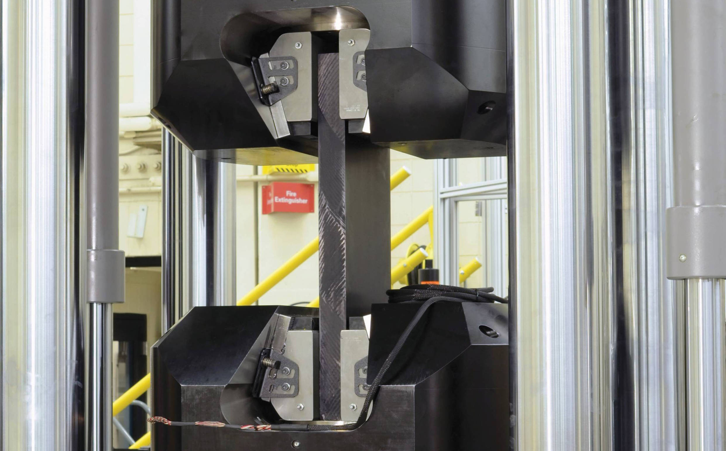
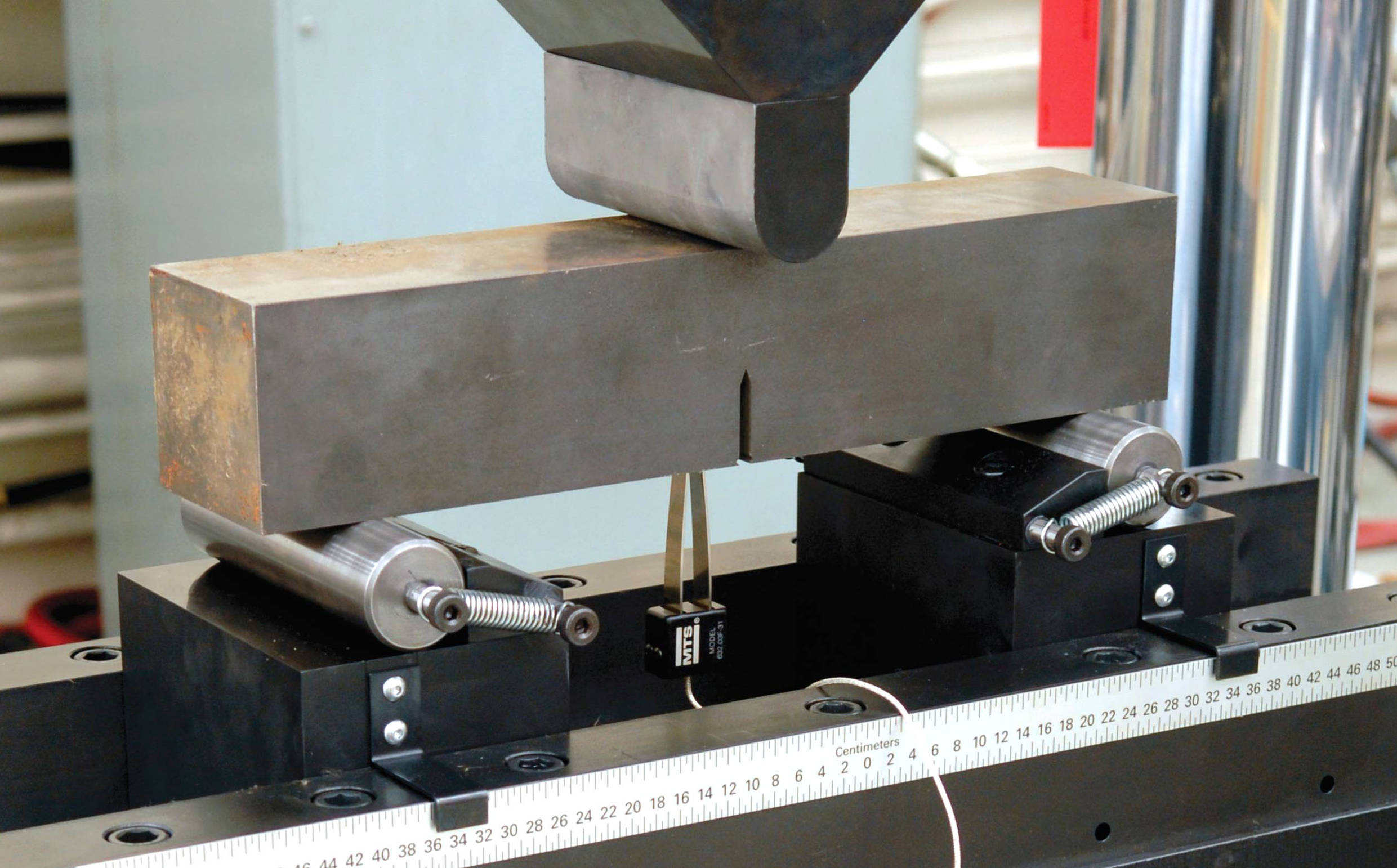
Optional High-Force Accessories - Compression Platens - Hydraulic Wedge Grips (shown) - Bend Fixtures - Custom Fixtures |
|
13. |
Crosshead Clamping Mechanism |
|
14. |
High-Performance MTS Actuator - Crosshead-mounted - High-Stiffness - Doubled-ended - Dynamically rated |
|
|
|
Standard Models |
Custom Models |
||||||
|
Load Frame Specifications |
Units |
311.31 |
311.32 |
311.41 |
311.51 |
311.61 |
311.71 |
311.81 |
311.91 |
|
Dynamic Force Ratings |
kN |
1000 |
1200 |
2500 |
5000 |
7500 |
10,000 |
20,000 |
30,000 |
|
(kip) |
(220) |
(265) |
(550) |
(1100) |
(1650) |
(2200) |
(4400) |
(6600) |
|
|
Standard Dynamic Strokes |
mm |
150, 250 |
150, 250 |
150, 300 |
300 |
Custom load frame dimensions vary according to customers' specific application requirements. Consult an MTS Applications Engineer for more information. |
|||
|
(in) |
(6, 10) |
(6, 10) |
(6,12) |
(12) |
|||||
|
Column Diameter |
mm |
101.6 |
101.6 |
152.4 |
203.2 |
||||
|
(in) |
(4.00) |
(4.00) |
(6.00) |
(8.00) |
|||||
|
Column Spacing (width) |
mm |
711.2 |
711.2 |
762 |
1016.0 |
||||
|
(in) |
(28.0) |
(28.0) |
(30.0) |
(40.0) |
|||||
|
Column Spacing (depth) |
mm |
406.4 |
406.4 |
508.0 |
812.8 |
||||
|
(in) |
(16.0) |
(16.0) |
(20.0) |
(32.0) |
|||||
|
Load Frame Height |
mm |
2946-5486 |
2946-5486 |
Note3 |
4470-8534 |
||||
|
(min-max) |
(in) |
(116-216) |
(116-216) |
Note3 |
(176-336) |
||||
|
Specimen and Grip Spacing |
mm |
254-2794 |
254-2794 |
Note2 |
450-4500 |
||||
|
(min-max) |
(in) |
(10-110) |
(10-110) |
Note2 |
(17.8-177) |
||||
|
Base Width (width) |
mm |
914.4 |
914.4 |
1066.8 |
1422.4 |
||||
|
(in) |
(36.0) |
(36.0) |
(42.0) |
(56.0) |
|||||
|
Base Width (including lifts) |
mm |
1219 |
1219 |
1492.5 |
1903 |
||||
|
(in) |
(48.0) |
(48.0) |
(58.8) |
(75.0) |
|||||
|
Base Depth |
mm |
1016 |
1016 |
1168.4 |
1397 |
||||
|
(in) |
(40.0) |
(40.0) |
(46.0) |
(55.0) |
|||||
|
Base Height (from floor) |
mm |
280.9 |
280.9 |
332 |
450 |
||||
|
(in) |
(11.06) |
(11.06) |
(13.06) |
(17.8) |
|||||
|
Hose Stand Spacing (max) |
mm |
921 |
921 |
2479 |
2479 |
||||
|
(in) |
(36.3) |
(36.3) |
(97.7) |
(97.7) |
|||||
|
Hose Stand Width |
mm |
991 |
991 |
991 |
991 |
||||
|
(in) |
(39.0) |
(39.0) |
(39.0) |
(39.0) |
|||||
|
Hose Stand Depth |
mm |
688 |
688 |
688 |
688 |
||||
|
(in) |
(27.1) |
(27.1) |
(27.1) |
(27.1) |
|||||
|
Hose Stand Height |
mm |
2426 |
2426 |
2819 |
3200 |
||||
|
(in) |
(95.5) |
(95.5) |
(111.0) |
(126.0) |
|||||
|
Approximate Crosshead Weight |
kg |
1225 |
1225 |
2903 |
7938 |
||||
|
(lb) |
(2700) |
(2700) |
(6400) |
(17,500) |
|||||
|
Approximate Total Weight |
kg |
4100 |
4100 |
9525 |
21500 |
||||
|
(lb) |
(9100) |
(9100) |
(21,000) |
(47,500) |
|||||
|
System Stiffness4 |
N/m |
1.6 X 10⁹ |
1.6 X 10⁹ |
3.1 X 10⁹ |
3.9 X 10⁹ |
||||
|
lbf/in |
9.3 X 10⁶ |
9.3 X 10⁶ |
17.4 X 10⁶ |
22.6 X 10⁶ |
|||||
|
1.Model 311.31 & 311.32 with actuator retracted, 311.41 & 311.51 with actuator at mid-stroke |
|
2.Model 311.41 150 mm stroke is 400 – 3000 mm (15.75 – 118.1 in), 311.41 300 mm stroke is 400 – 3385 (13.31 – 133.3 in) |
|
3.Model 311.41 150 mm stroke is 3554 – 6154 (140.0 – 242.3 in), 311.41 300 mm stroke is 3720 – 6768 (146.5 – 266.5 in) |
|
4.Stiffness calculated at a crosshead height of 2 meters (78.7 inch) above the base. |
Service and Support
Our experts are here to help keep you up and running.
Related Products, Parts or Accessories
Landmark® Servohydraulic Test Systems
TestSuite Software
SilentFlo™ 515 Hydraulic Power Units (HPU)
Looking for more products?
Go to Solution FinderCONTACT US TODAY
Ready for a quote or need more information? We're here to help. Request A QuoteResources
Retos de las prueba de alta fuerza
Los ingenieros de aplicaciones de MTS analizan los matices y…
Uso de C3 Performance para acelerar pruebas estructurales complejas
Casos de uso; NIAR y NRC- Canada
Prueba de barras de refuerzo de ultra alta resistencia
Cumplir con los requisitos de las pruebas de barras de refue…
Proteger el buen estado del sistema hidráulico
Descubra las ventajas del programa Cuidado de fluidos de MTS
El caso de la calibración
La calibración de MTS puede ayudar a aumentar la validez de …
8 % más de eficiencia energética
Reduzca los costos operativos de la HPU SilentFlo 505 gracia…